Order of the Fitch

Emblem of the Order - Part 3

In our previous instalment, we dipped our toes in and starting exploring the basic tools for drawing vector contours in EnRoute. Today, we will continue our exploration by learning to “mirror” and “weld” contours.

Drawing The Boar’s Crown

We will start drawing the crown with the rectangle tool. Place one corner at the bottom left of the crown and click a second time on the centre point of the crown. Then switch to the edit points tool and select the top left corner of your rectangle — move it over to the crown’s left-most point. Next, right click anywhere on the top of the rectangle. Choose “insert point” and create a new point. Do this two more times, then move the new points to finish drawing half of the crown.

Screen Shot 2021-03-01 at 3.07.53 PM.png
Screen Shot 2021-03-01 at 3.09.26 PM.png

Mirroring Contour shapes

After completing the half-crown select it with the select objects tool. Next, choose “mirror” from the “transform” drop-down menu.

Screen Shot 2021-03-01 at 3.09.42 PM.png
Screen Shot 2021-03-01 at 3.10.01 PM.png

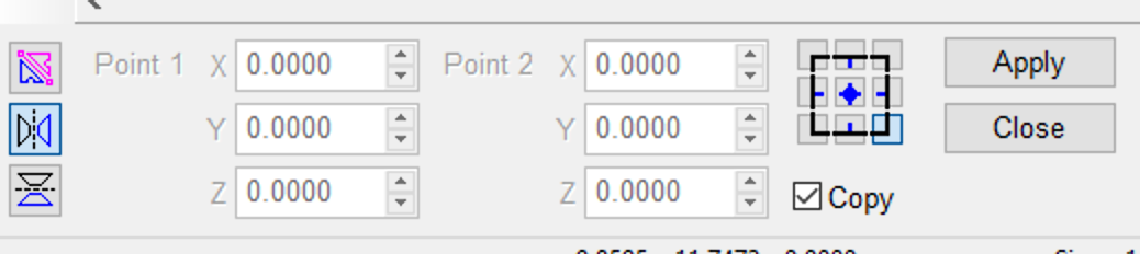
A dialogue box will appear at the lower left of your screen. Make sure “mirror horizontal” and “copy” are toggled on. By default it will mirror from the bottom-left corner so be sure to mirror from the top-right, middle-right, or bottom-right (as you can see, I used the bottom-right).

Screen Shot 2021-03-01 at 3.10.57 PM.png

Clicking apply creates a mirrored copy of the half-crown. All that remains is to weld these two half-crowns together into a single polyarc.

Welding Contour Shapes

Select both half-crowns with the select objects tool before activating the “weld joined” tool. This tool will merge any two closed polyarcs as long as they overlap (or share an edge).

Screen Shot 2021-03-01 at 3.12.22 PM.png
Screen Shot 2021-03-01 at 3.12.32 PM.png

As you can see, mirroring and welding polyarcs is a quick way to create almost any symmetrical shape. In fact, this is yet another method we could have used to create the shield we drew last time.

Next up, we will look at drawing polyarcs with “Bezier curves.”

Emblem of the Order - Part 2

In part one of this series, we opened a new file and imported our reference sketch. In this instalment, we will look at a couple ways to draw some vector contours.

Drawing (a Shield) With Polyarcs

Before we start drawing our vector contours, we should make sure we have “snap to endpoints” toggled on. (This is by far the most useful snap and I almost always have it enabled.)

With that bit of housekeeping out of the way, we can take a look at our first drawing tool — “draw polyarc.”

Screen Shot 2021-03-01 at 2.31.00 PM.png
DRAW POLYARC MAR 1

I started by clicking once on the top left corner (of the sketched shield) then moved to the top right and bottom corners — the polyarc tool draws a line between your corners. I clicked one last time on my starting corner to finish the shape. Because we have “snap to endpoint” toggled, our polyarc becomes a “closed contour.”

Screen Shot 2021-03-03 at 12.43.57 PM.png
TRIANGLE MAR 1

Obviously however, our contour isn’t exactly shield shaped at the moment…

Editing Contour segments

Happily, curving the shield’s edges is a straightforward process. We will use the (erroneously named?) “edit points” tool to edit our lines. Simply click and hold anywhere on a line and pull it — it automatically changes from a line into an arc!

EDIT POINTS MAR 1
TRIANGLE SHIELD MAR 1

Incidentally, you can see why I chose to import a green version of my sketch; my contour lines/arcs are clearly visible. They would be nigh impossible to see if I had used my original black and white sketch.

Drawing (A Shield) With Shapes

As you can see, “draw polyarcs” and “edit points” are a handy pair of tools. However, I would like to show you a second drawing method — it requires a few more steps but, as you will see, it can be useful when you want a little more accuracy.

Select the “rectangle” tool and click on one of the shield’s top corners — then drag down diagonally and click again to form the rectangle shown below.

Screen Shot 2021-03-01 at 1.32.12 PM.png
Screen Shot 2021-03-01 at 1.36.11 PM.png

Notice that the shield’s two upper corners are automatically lined up at the same height.

Editing Contour segments (Again)

Select Objects

Select Objects

Now draw a second rectangle by clicking on the previous rectangle’s bottom left corner. Drag the new rectangle out and click again. Now, choose the “select objects” tool and click and hold on the midpoint of the right side of your new rectangle. Then drag the curser to the bottom right corner of the original rectangle and release — the new rectangle is now exactly as wide as the old one.

Screen Shot 2021-03-02 at 10.23.43 PM.png
Screen Shot 2021-03-02 at 10.25.08 PM.png

Next, press F2 to open the precision input center, type “/2” into the width box and click OK — your new rectangle is now exactly half the width of the old one.

Screen Shot 2021-03-02 at 10.15.13 PM.png
SMALL BOX MAR 1

At this point, you can switch to the edit points tool and move the original rectangles bottom right corner until it snaps to the new rectangle’s bottom right corner (this places the shield’s bottom corner exactly in the middle). Now, switch back to the select objects tool and delete the smaller rectangle.

PART TRIANGLE MAR 1
NO BOX MAR 1

Lastly, switch back to the edit points tool one more time to select and delete the bottom left corner. Notice that this creates an arc. As with the previous method — click, hold and drag the lines/arcs to finish shaping the shield. As you can see, this method allows us to be a little more precise about where we place our shield’s corners.

Screen Shot 2021-03-02 at 10.17.39 PM.png
ANOTHER SHEILD MAR 1

In our next instalment, we will trace the crown and look at mirroring and joining contour shapes.

Emblem of the Order - Part 1

The Order of the Fitch

One of the few “duties” of a loyal member of the Order of the Fitch is to design and build a personal Emblem of the Order. Every member’s emblem is unique, with the exception of two features. First, each emblem should have a pseudo-chivalric air. Second, each design must incorporate a fitch and a mahlstick.

This “introductory series” will follow the design and construction of my personal Order Emblem and will focus, as much as possible, on the fundamentals of the process.

Order+of+the+Fitch+Feb+24.jpg

Designing an Emblem

I roughed out my emblem design in Procreate, opting for a simple wooden shield, encircled by a belt and backed with a crossed fitch & mahlstick. A crowned boar’s head will be emblazoned on the shield (a nod to the traditional hog bristle fitch).

My emblem’s design will be relatively straightforward to build in EnRoute — the belt will be the most challenging element (because it wraps around the shield). We will take the time to explore at least one or two ways to build each element. By the time we are finished, you should have a basic grasp of a handful of the program’s capabilities.

Opening a New File

New File Mar 1

With our design in hand, we can start a new file in EnRoute. We will keep the finished emblem relatively small (no more that 2’ across and 2” thick). I have defined my “plate” (the area to be routed) as 24” x 24” x 2” and set the “surface” to the top of the plate. These parameters can all be changed later.

I am working with imperial units (although Canada uses the metric system, imperial units continue to be used in the construction industry), but you can also choose metric units when you install EnRoute.

Importing a Bitmap

Import Mar 1.png

Next, we will import the design sketch. EnRoute will import .bmp, .jpg and .pdf images. You will notice that I imported a light green version of the sketch — this will be helpful later.

With the design selected, press F2 to open the “Precision Input Centre.” Ensure “Proportional” is checked before entering an appropriate width or height to resize the sketch.

resize mar 1

Creating Contours

Now we are ready to start creating the vector “contours” we will use to build our 3D “reliefs.”

There are a number of ways to create contours. For instance, if our sketch was tighter/cleaner/darker, we could trace it with Enroute’s “vectorize bitmap” function. Alternately, we could have created the vector contours in Illustrator and imported them directly (eliminating the need to import the sketch). Instead, to create our basic contours, we will simply trace the line work by hand.

In our next instalment, we will look at a few ways to draw vector contours in EnRoute.